
Grounding Grid Design for Substations: Key Engineering Considerations
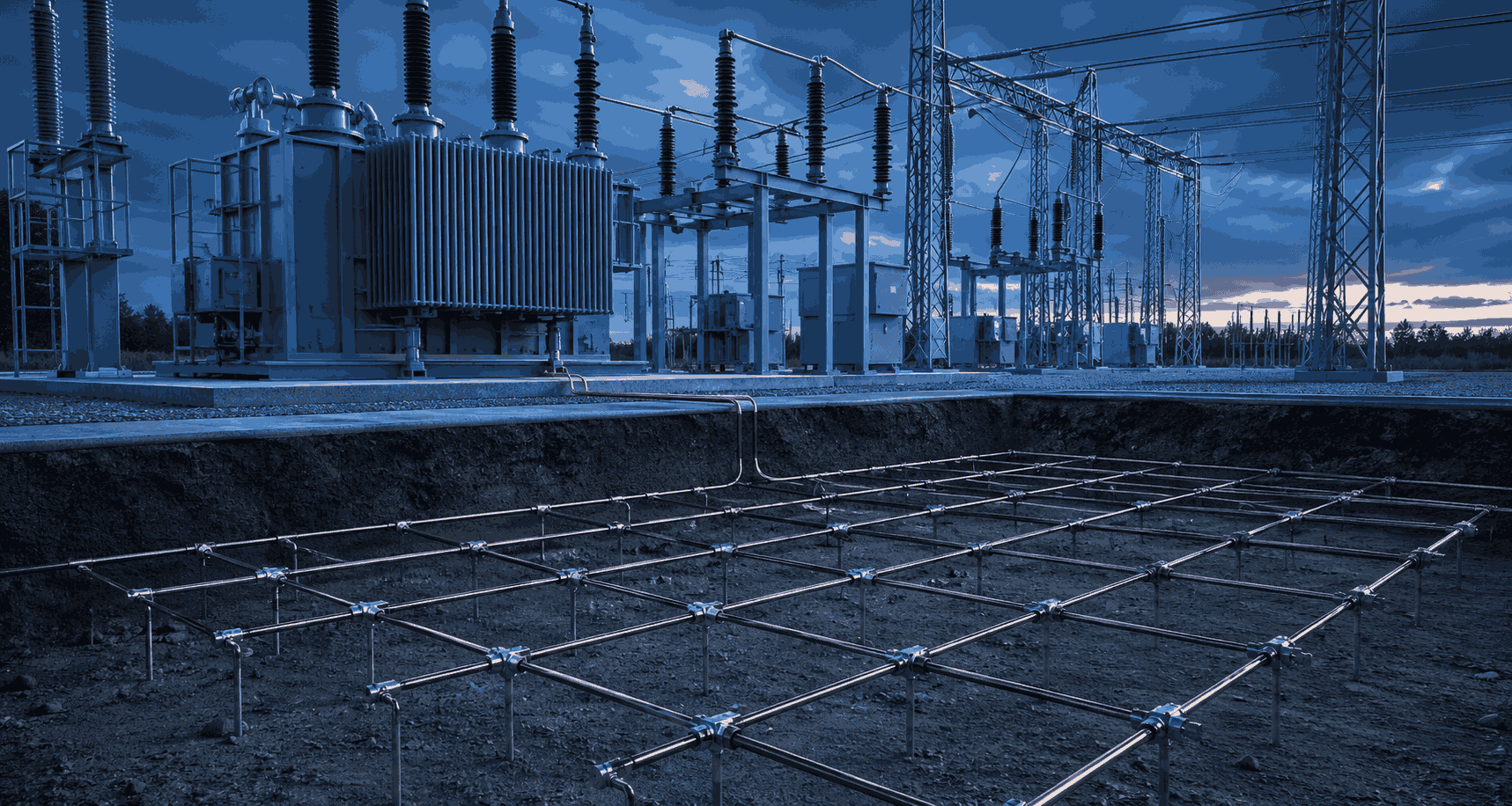
A worker touches a de-energized cabinet during a fault on an adjacent circuit and receives a shock anyway. A grounding system passes visual inspection for years, then fails a resistance test the first time anyone actually measures it. A perfectly sized grid on paper turns out to be undersized the moment the utility revises its fault current data.
None of these are equipment failures in the traditional sense. They’re the direct, predictable result of substation grounding grid design that wasn’t engineered to hold up under real fault conditions — and they’re some of the most dangerous gaps to leave unaddressed, because a grounding system rarely announces that it’s failing until someone is standing on it during a fault.
Substation grounding grid design is the engineering process of sizing and laying out a network of buried conductors and ground rods so that fault current has a low-impedance path back to source, and so that touch and step voltages at the surface stay within safe limits for anyone standing in or near the substation during a fault. Done correctly, it protects both personnel and equipment. Done poorly, it can look identical from above ground while quietly failing the one job it has.
This guide breaks down what actually goes into a sound grounding grid design, the problems that show up most often in real substation projects, and how to build a design approach that holds up under both routine testing and worst-case fault conditions.
What Is Substation Grounding Grid Design?
Substation grounding grid design is the process of engineering a buried network of interconnected conductors and ground rods beneath and around a substation so that fault current dissipates safely into the earth, rather than through equipment, structures, or people.
Need Engineering Support for Your Power Project?
American Power Engineers delivers power system studies, substation design, renewable energy engineering, BESS projects, NERC compliance, MEP engineering, and POI interconnection services.
Explore Our Engineering ServicesNeed Engineering Support for Your Substation Project?
American Power Engineers delivers power system studies, substation design, renewable energy engineering, BESS projects, NERC compliance, MEP engineering, and POI interconnection services.
It’s governed primarily by IEEE Std 80, which sets out the analysis methods for calculating safe touch and step voltage limits and for verifying that a proposed grid design meets them under actual site and fault conditions.
In practice, this means:
- Soil resistivity testing and modeling — measuring actual site soil resistivity (typically via the Wenner four-pin method) rather than assuming a textbook value, since resistivity drives every downstream calculation.
- Fault current and clearing time analysis — using the maximum available ground fault current and the protection system’s actual clearing time to determine how much energy the grid needs to safely dissipate.
- Grid conductor sizing and layout — selecting conductor size, spacing, burial depth, and mesh pattern so that grid resistance and surface voltage gradients stay within IEEE 80 safety limits.
- Touch and step voltage verification — calculating the maximum touch and step voltages a person could be exposed to at the substation perimeter and within the fence line, and confirming they fall below tolerable limits for the fault clearing time in use.
Why Substation Grounding Grid Design Matters
Grounding design isn’t a formality tucked into the civil scope — it’s one of the few substation systems where a design error translates directly into a life-safety hazard, not just a reliability issue.
- It’s the primary defense against lethal touch and step voltages. During a ground fault, current flowing through the earth creates voltage gradients at the surface. A properly designed grid keeps those gradients below the threshold the human body can safely withstand for the fault’s clearing time.
- It protects equipment, not just people. Excessive ground potential rise (GPR) during a fault can damage control cables, communication equipment, and electronic relays that reference a “clean” ground — grounding design and equipment protection are linked, not separate concerns.
- Soil conditions are project-specific, not assumable. Two substations built to the same electrical specification can require very different grid designs if their soil resistivity, moisture content, or seasonal frost depth differ — this is one of the most common places generic designs fail in the field.
- It’s a NERC and OSHA compliance issue, not just a design preference. Grounding system integrity feeds into facility safety programs and, for BES-connected substations, into broader reliability and worker-safety obligations that get scrutinized during audits and after incidents.
- Rising fault current levels from grid growth and new interconnections can outpace an existing grid’s design margin. A grid engineered for the fault current available at commissioning may no longer meet safety limits once new generation, load, or transmission upgrades increase available fault current at that bus.
Common Substation Grounding Grid Design Problems — And How to Solve Them
Most grounding grid problems we see aren’t caused by engineers misunderstanding IEEE 80. They’re caused by predictable gaps in how site data is gathered, how designs are verified, and how grids are maintained after energization.
Problem: Soil resistivity was assumed instead of measured.
Using a generic or “typical” soil resistivity value instead of actual site testing is one of the most common and most consequential shortcuts in grounding design. Soil resistivity can vary significantly across a single site depending on moisture, layering, and composition, and a design based on the wrong value can be dangerously undersized without anyone realizing it until a resistance test fails.
Planning a Solar, Wind, BESS, or Grid Interconnection Project?
Our engineering team helps project owners, developers, utilities, and facility teams move from technical planning to reliable project execution.
View Engineering ServicesPlanning a New Substation or Upgrading an Existing Grounding System?
Our engineering team helps project owners, developers, utilities, and facility teams move from technical planning to reliable project execution.
Solve it by performing Wenner four-pin soil resistivity testing at multiple points and depths across the actual site, and using a layered soil model in the grid analysis rather than a single uniform resistivity assumption.
Problem: The grid design used outdated or conservative fault current data.
A grounding grid sized against fault current data from early in a project — or against a conservative placeholder value — can fall out of alignment once interconnection studies, generation additions, or utility system upgrades change the actual available ground fault current at that bus.
Solve it by confirming the ground fault current and protection clearing time used in the grounding analysis against the final, utility-confirmed short circuit study, and re-verifying the grid design any time fault current assumptions materially change.
This is the same underlying fault current data used in a facility’s broader power system studies, which is why grounding design should never be scoped as a standalone calculation.
Problem: Touch and step voltage checks weren’t verified at the fence line and equipment access points.
It’s common to see grid designs that meet safety limits at the geometric center of the grid but weren’t explicitly checked at the perimeter fence, gate areas, and equipment access points — exactly where personnel are most likely to be standing during a fault.
Solve it by running touch and step voltage checks at the fence line, all gates, and every equipment maintenance access point, not just representative interior nodes, and treating any location that fails as a design deficiency requiring additional grounding, not a documentation footnote.
Problem: Grid conductor sizing didn’t account for the full fault duration and X/R ratio.
Undersized grid conductors can thermally withstand a fault for a shorter duration than the protection system actually takes to clear it, particularly when backup protection clearing times — not just primary clearing times — are the realistic worst case.
Solve it by sizing grid conductors against the maximum credible fault duration, including backup protection clearing time, and using the site’s actual X/R ratio in the calculation rather than a simplified assumption.
Problem: The grounding system was never re-verified after site or system changes.
A grounding grid designed and tested at commissioning reflects the system as it existed at that point. Site regrading, new buried utilities, added equipment pads, or upgraded fault current levels can all change the grid’s effective performance without any visible sign above ground.
Solve it by treating grounding grid verification as a living requirement tied to periodic resistance testing and to any material site or system change not a one-time deliverable filed away after commissioning.
Need Engineering Support for a New Substation or Interconnection Project?
Our team performs grounding grid design, soil resistivity analysis, and touch/step voltage verification for utility-scale substations, industrial facilities, and renewable interconnections. See our ERCOT interconnection services for region-specific grounding and interconnection support across Texas’s deregulated grid.
Building a Grounding Grid Design That Holds Up
A substation grounding grid design that stays reliable over the life of the facility generally includes five components:
- Site-specific soil data. Multi-point, multi-depth Wenner resistivity testing, modeled as layered soil rather than a single assumed value.
- Confirmed fault current and clearing time inputs. Ground fault current and protection clearing times pulled from the final, utility-confirmed short circuit study — not an early-stage placeholder.
- Full-site touch and step voltage verification. Checks performed at the fence line, gates, and equipment access points, not just interior grid nodes.
- Conductor and rod sizing with margin. Grid conductors and rods sized against worst-case fault duration, including backup clearing time and actual X/R ratio.
- A defined re-verification trigger. Periodic resistance testing, plus a review any time fault current levels, site grading, or buried infrastructure changes materially.
Substations designed with this discipline from the start typically avoid the two most expensive and most dangerous outcomes: a grounding system that fails a resistance test years after commissioning, and a design that was technically compliant on paper but never verified against the site’s actual fault current or soil conditions.
How American Power Engineers Supports Substation Grounding Grid Design
American Power Engineers provides the engineering foundation for substation grounding systems, from initial soil analysis through commissioning support.
Our work includes:
- Soil resistivity testing coordination and layered soil modeling
- IEEE 80–based grounding grid design and conductor sizing
- Touch and step voltage analysis across the full site, including fence lines and access points
- Ground potential rise (GPR) evaluation for equipment and communication protection
- Grounding system re-verification tied to interconnection and system changes
- Field resistance testing support and remediation design for underperforming grids
We support HV/MV substation projects for utilities, developers, and EPCs across every major North American interconnection footprint, and we build grounding designs as an integrated part of the full substation design process rather than a late-stage add-on. For the full scope of our substation work, visit our Substation Design engineering services page.
FAQs
What standard governs substation grounding grid design?
IEEE Std 80 (“IEEE Guide for Safety in AC Substation Grounding”) is the primary reference standard. It defines the methods for calculating tolerable touch and step voltages, soil resistivity modeling, and grid resistance, and most utility and NERC-adjacent grounding requirements are built around its methodology.
How deep should a substation grounding grid be buried?
Most grids are buried between 18 inches and 3 feet, depending on soil conditions, frost depth, and mechanical protection requirements — this comes up constantly in field discussions among engineers because “standard depth” varies more by region and frost line than most generic guidance suggests. The correct depth is determined by the site-specific soil model and frost data, not a single universal number.
What’s the difference between a grounding grid and a ground mat or ground rod system?
A grounding grid is a network of interconnected buried conductors forming a mesh across the substation footprint. A ground mat typically refers to a smaller, localized grid section (often at an operator standing position), and ground rods are vertical electrodes, usually connected into the grid, used to reach lower-resistivity soil layers or reduce localized resistance. Most substations use all three together as one integrated system.
Why does soil resistivity matter so much in grounding design?
Soil resistivity directly determines how much grid conductor, how many ground rods, and how large a grid footprint are needed to achieve a safe ground resistance and acceptable touch/step voltages. High-resistivity soil (dry, sandy, or rocky) generally requires a larger or more heavily rodded grid than low-resistivity soil, and assuming the wrong value is one of the most common causes of underperforming designs.
How often should a substation’s grounding system be tested?
There’s no single universal interval — testing frequency should be driven by facility criticality, soil conditions, and any site changes, but many facilities perform ground resistance testing every 1 to 3 years as part of routine maintenance, with additional testing triggered by regrading, new construction, or a suspected grounding issue.
Can an existing substation’s grounding grid be upgraded without a full excavation?
In many cases, yes. Supplemental ground rods, additional radial conductors tied into the existing grid, or targeted soil treatment (such as ground enhancement material) can improve performance without excavating the entire grid. The right approach depends on what the resistance testing and touch/step voltage analysis show is actually deficient.
Work With American Power Engineers
Expert engineering support for substation grounding grid design, substation design, power system studies, and interconnection services.
Related Services:
- Substation Design Engineering
- Power System Studies
- POI Interconnection Engineering
- NERC O&P 693 Compliance Services
Related Reading:
Work With American Power Engineers
Expert engineering support for power system studies, substation design, renewable energy projects, BESS engineering, NERC compliance, MEP engineering, and POI interconnection services.
Explore All Engineering Services