
Grid Connection Consulting
Connection Strategy, Works Offers, and ISO Navigation Without the Surprises
End-to-end grid connection advisory for renewable energy developers, utilities, and independent power producers from feasibility assessment through to energisation across Australia’s NEM, US ISOs, and the United Kingdom.
Melbourne, Australia (HQ) · AEMO · NEM · ERCOT · PJM · National Grid ESO · Licensed Engineers
2009
Established
3
Continents
6
Grid Markets
10
Software platforms
Technologies
Solar Wind BESS
Lifecycle
Project Coverage
The Connection Offer That Changed the Project Budget
The connection offer arrived. $4.2 million in network augmentation works. The developer had modelled yield, revenue, and IRR, but nobody had modelled what the network required the project to pay for. The system strength assessment was not completed at feasibility, and the works offer was not independently evaluated before the developer committed to the connection timeline. The network service provider’s cost allocation included shared augmentation charges that were not challenged or verified against the applicable cost-sharing framework. This was not a technical failure. The power system studies were correct, the design was sound, and the engineering deliverables were professionally executed. But the grid connection strategy the advisory work that determines whether a project connects on time, on budget, and without costly surprises was either absent or incomplete. This is a grid connection consulting problem. Not a design problem. Grid connection engineering is not a single study or application. It is a multi-year process involving network analysis, regulatory engagement, commercial evaluation, and ongoing condition management across grid operators, network service providers, and market bodies, each with its own requirements, timelines, and approval processes. Since 2009, American Power Engineers has managed this process for solar, wind, BESS, hybrid, and large load projects across Australia’s NEM, US ISOs including ERCOT, PJM, CAISO, and MISO, and the United Kingdom under National Grid ESO rules. Every project we have supported was connected because the grid connection strategy was right not just because the engineering studies were correc

What Grid Connection Consulting Actually Covers
Grid connection consulting is the engineering advisory layer that sits above and alongside the design process. It covers every decision that determines whether a project receives a connection offer, whether the terms of that offer are commercially acceptable, and whether the project ultimately energises within the developer’s financial close and PPA timelines.
Connection Strategy Development
Before a connection application is submitted, the connection strategy determines the technical and commercial viability of the project. This includes:
Point of Connection (POC) Assessment
Evaluate available connection points, network capacity, system strength, and augmentation liability while comparing connection cost, timeline, and technical risk.
Feasibility-Stage Network Analysis
Conduct preliminary load flow, fault level, and thermal assessments to identify network constraints and determine whether capacity, POC, or voltage adjustments are required.
Connection Application Strategy
Define the optimal application timing, application class, and supporting documentation to maximise the likelihood of receiving a commercially acceptable connection offer.
Financial Model Alignment
Integrate connection costs, augmentation estimates, timeline assumptions, and system strength contingencies into the developer's financial model.
Connection Application Management
Once the strategy is established, we manage the technical engagement required throughout the application process.
AEMO NEM Connection Applications
Manage connection enquiries, applications, Rule 5.3 processes, technical submissions, and AEMO assessment responses.
US ISO Interconnection Requests
Prepare applications and manage queue participation for ERCOT, PJM, CAISO, MISO, NYISO, SPP, and ISO-NE, including model submissions and deficiency responses.
National Grid ESO Applications (UK)
Manage applications under CUSC and the GB Grid Code, including Statement of Works assessments and queue strategy.
SWIS / Western Australia
Coordinate connection applications under Western Power standards and the ERA regulatory framework.
Works Offer Evaluation & Negotiation
A works offer defines connection costs, required infrastructure, and project obligations before energisation. We provide an independent technical review to ensure the offer is commercially and technically justified.
Cost Allocation Verification
Assess whether augmentation costs comply with the applicable cost-sharing framework.
Shared Augmentation Analysis
Identify costs that should be shared with other connecting parties or funded through regulated investment.
Technical Scope Review
Verify that the required network works are appropriate for the requested connection capacity.
Challenge & Alternative POI Strategy
Develop challenge strategies or alternative connection options where offer terms are commercially unacceptable.
AEMO / ISO Liaison & Technical Engagement
Grid connection requires continuous technical coordination with market operators and network service providers throughout the project.
AEMO Technical Assessments
Manage responses to AEMO assessments, GPS reviews, and system strength queries.
Network Service Provider (NSP) Engagement
Coordinate with TNSPs and DNSPs on protection, metering, operational readiness, and connection design.
ISO Study Processes
Participate in cluster studies, system impact studies, facility studies, and manage model submissions and restudies.
Multi-Party Coordination
Coordinate technical engagement where multiple generators share connection points or compete for network capacity.
Connection Condition Management
Connection agreements create ongoing obligations that continue before and after energisation. We manage these requirements throughout the project lifecycle.
Pre-Energisation Conditions
Manage GPS compliance, protection systems, metering, SCADA, communications, and outstanding technical obligations.
Registered Parameter Management
Establish and monitor registered generating system parameters throughout operation.
Post-Energisation Compliance
Support ongoing GPS compliance, parameter verification, and operational condition management.
Connection Agreement Modifications
Manage agreement amendments resulting from plant upgrades, technology changes, or operating mode modifications.
Grid Connection Expertise Across Six Markets
American Power Engineers delivers specialist grid connection consulting across six major electricity markets spanning three continents. We help renewable energy developers, investors, and EPC contractors navigate every stage of the grid connection process, from early feasibility assessments and connection strategy to regulatory approvals and final energisation. Our team understands the unique regulatory frameworks, technical standards, and application requirements of each market, enabling us to develop practical and commercially focused connection solutions. By combining cross-market experience with proven engineering expertise, we reduce technical risk, streamline approval processes, and support efficient project delivery. Whether your project involves solar, wind, BESS, or hybrid energy systems, we provide the technical guidance and strategic advisory needed to achieve reliable, compliant, and cost-effective grid connections that align with your project objectives and long-term investment goals.

Grid Connection Expertise Across Six Markets
Jurisdiction
QLD, NSW, VIC, SA, TAS
Governing Body
AEMO + TNSPs/DNS Ps
Connection Framework
NER Chapter 5, Rule 5.3
Key Standards
NER S5.2, AEMO GPS, AS/NZS 4777
APE Capability
Feasibility energisation. Connection applications, GPS compliance, works offer evaluation, registered parameter management
Jurisdiction
Western Australia
Governing Body
Western Power + ERA
Connection Framework
WA Access Arrangement, Technical Rules
Key Standards
Western Power Technical Rules, ERA requirements
APE Capability
Connection strategy, works offer review, ERA regulatory navigation. SWIS framework differs substantially from NEM.
Jurisdiction
Texas, USA
Governing Body
ERCOT
Connection Framework
ERCOT Interconnecti on Process
Key Standards
NERC O&P, ERCOT Operating Guides, IEEE 2800
APE Capability
Interconnecti on request management, cluster study participation, dynamic model submission, PRC-029-1 compliance.
Jurisdiction
13 US states + DC
Governing Body
PJM Interconnecti on LLC
Connection Framework
PJM OATT, FERC Order 2023
Key Standards
NERC O&P, PJM Manuals, FERC requirements
APE Capability
Queue management, system impact study participation, facilities study coordination, cost allocation review.
Jurisdiction
California, USA
Governing Body
CAISO
Connection Framework
CAISO Interconnecti on Process
Key Standards
NERC O&P, CAISO BPM, FERC Order 2023
APE Capability
Cluster study management, deliverability assessment, full capacity deliverability status strategy.
Jurisdiction
15 US states + Manitoba
Governing Body
MISO
Connection Framework
MISO Generator Interconnecti on
Key Standards
NERC O&P, MISO BPM
APE Capability
Definitive Planning Phase (DPP) management, network upgrade cost analysis, queue navigation.
Jurisdiction
New York, USA
Governing Body
NYISO
Connection Framework
NYISO OATT
Key Standards
NERC O&P, NYISO manuals
APE Capability
Interconnecti on study management, Class Year study participation, deliverability assessment
Jurisdiction
United Kingdom
Governing Body
National Grid ESO
Connection Framework
CUSC, GB Grid Code
Key Standards
IEC standards, Ofgem framework, GB Grid Code
APE Capability
Connection application, Statement of Works, GB queue strategy, Grid Code compliance.
Australia's National Electricity Market
The AEMO NEM connection process is one of the most complex grid connection pathways for renewable energy projects in Australia. It requires coordination with AEMO, TNSPs, and DNSPs through multiple assessment stages while ensuring compliance with GPS, registered parameters, protection systems, metering, and SCADA requirements.
What Makes It Complex?
Unlike US ISO markets, the AEMO NEM assesses each connection application individually rather than through a cluster study process. Changing network conditions, system strength, marginal loss factors, and augmentation requirements can significantly impact project costs, timelines, and connection outcomes.
Our Advisory Covers
- Pre-Application : POC assessment, feasibility-stage network analysis, GPS pre-assessment, system strength screening, and financial model alignment.
- Connection Application : Application preparation, AEMO technical data submissions, and NER Chapter 5.3 process management.
- AEMO Assessment : Response management for assessment reports, GPS preliminary assessments, and system strength impact assessments.
- NSP Engagement : Works offer evaluation, cost allocation review, and coordination with TNSPs and DNSPs.
- Connection Agreement : Agreement review, condition negotiation, and registered parameter establishment.
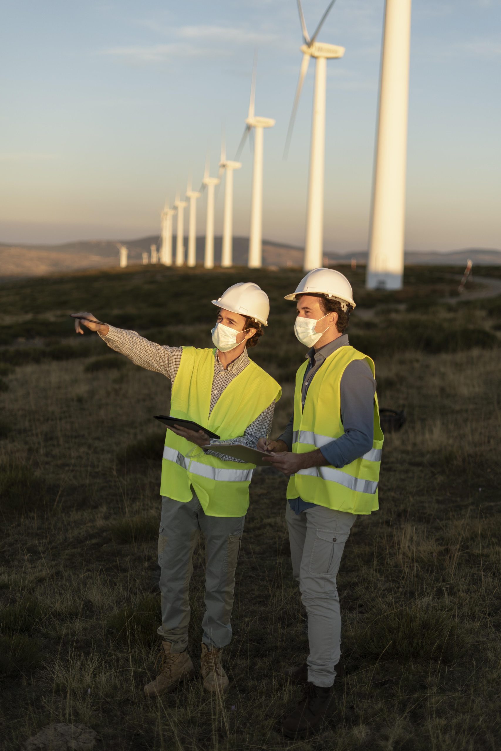

ERCOT, PJM, CAISO, MISO
US ISO Interconnection
The US interconnection landscape has changed significantly following FERC Order 2023. Although queue reforms have improved processing, developers still face complex study procedures, technical submissions, cost allocation reviews, and project timelines. Each ISO follows its own interconnection framework, making market-specific expertise essential for successful project delivery.
What Makes It Complex?
Every ISO operates with different application procedures, study methodologies, technical standards, and cost allocation frameworks. Experience in one market does not automatically apply to another. Developers managing projects across multiple US markets require specialist knowledge to navigate each ISO efficiently and minimise project delays.
Our Advisory Covers
- ERCOT – Interconnection request preparation, planning model submission, dynamic model validation, study management, and connection agreement support.
- PJM – Queue management, system impact studies, facilities studies, FERC Order 2023 transition support, and ISA review.
- CAISO – Cluster study management, Phase I & II studies, deliverability assessments, FCDS strategy, and cost allocation review.
- MISO – Definitive Planning Phase (DPP) management, network upgrade cost assessment, and queue strategy.
United Kingdom
National Grid ESO
The UK grid connection process operates under the Connection and Use of System Code (CUSC) and the GB Grid Code. Connection applications are assessed by National Grid ESO while transmission access is managed by the relevant Transmission Owner (TO). With ongoing queue reforms and increasing renewable energy projects, developers require specialist guidance to successfully navigate regulatory requirements and technical assessments.
What Makes It Complex?
The UK connection framework combines detailed Grid Code compliance, Statement of Works assessments, transmission planning, and evolving queue management policies. Projects must meet strict technical requirements while maintaining commercially viable delivery schedules, making experienced grid connection advisory essential.
Our Advisory Covers
- Connection Applications – Preparation and submission under CUSC requirements.
- Statement of Works – Technical assessment and review.
- GB Grid Code – Compliance planning and technical advisory.
- Connection Agreements – Review, negotiation, and regulatory guidance.
- Queue Strategy – Support for evolving National Grid ESO connection reforms.
- Project Delivery – Technical coordination through to final grid energisation.

Our Grid Connection Consulting Process
American Power Engineers manages every stage of the grid connection lifecycle through a structured six-phase process. From initial feasibility assessments to post-energisation compliance, each phase includes clearly defined deliverables, technical milestones, and client engagement to minimise risk and support successful project delivery.
Feasibility & Site Assessment

Evaluate project feasibility, network capacity, and technical risks before submitting a connection application. Early planning helps reduce uncertainty, improve cost estimates, and support informed investment decisions.
What We Do
- Evaluate candidate Points of Connection (POC)
- Review network capacity and voltage levels
- Perform load flow and fault level screening
- Assess system strength and GPS risks
- Estimate connection costs and timelines
- Align findings with the project financial model
Deliverable
Feasibility Connection Assessment Report including POC recommendations, network analysis, cost estimates, timeline projections, and identified risks.
Connection Application Preparation

Prepare a complete connection application with all required technical documentation, engineering models, and supporting data to improve assessment quality and reduce approval delays.
What We Do
- Prepare connection enquiries and applications
- Develop single-line diagrams
- Compile equipment specifications
- Submit dynamic models and GPS data
- Coordinate with EPC contractors
- Validate technical documentation
Deliverable
Assessment & Study Management

Manage technical assessments, study responses, and coordination with grid operators to keep the connection process moving efficiently through every review stage.
What We Do
- Respond to AEMO and ISO technical queries
- Participate in system impact studies
- Manage facility and cluster studies
- Resolve technical deficiencies
- Track study milestones and queue position
- Coordinate multi-party technical engagement
Deliverable
Works Offer
Evaluation

Review the connection offer to verify technical scope, cost allocation, and commercial obligations before the agreement is accepted.
What We Do
- Review works offer scope
- Verify cost allocation
- Assess augmentation costs
- Review connection conditions
- Evaluate alternative connection options
- Support agreement negotiations
Deliverable
Works Offer Evaluation Report with technical review, cost analysis, condition assessment, and negotiation recommendations.
Pre-Energisation Compliance

Ensure every technical and regulatory condition is completed before energisation, reducing commissioning risks and supporting compliance.
What We Do
- Manage GPS compliance
- Complete model validation
- Verify protection systems
- Confirm metering and SCADA readiness
- Establish registered parameters
- Coordinate EPC commissioning activities
Deliverable
Energisation & Post-Connection Support
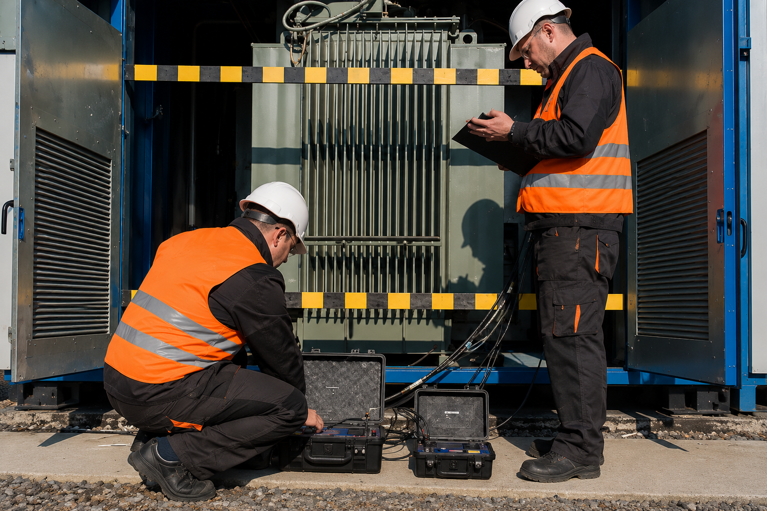
Provide ongoing technical support during energisation and commercial operation while maintaining long-term compliance with connection requirements.
What We Do
- Support energisation activities
- Verify registered parameters
- Monitor GPS compliance
- Manage connection conditions
- Process agreement modifications
- Provide ongoing technical advisory
Deliverable
Grid Connection Consulting Deliverables
Every engagement produces defined, documented deliverables. These are not summary emails or presentation decks. They are technical documents that developers, lenders, legal teams, and regulators rely on for decision-making.
Feasibility Connection Assessment Report
POC evaluation, preliminary network analysis, connection cost estimate, timeline projection, risk identification
Typical Recipient
- Developer
- Investor
- Lender
Format
PDF report (30–60 pages)
Connection Application Package
Complete application with technical data, single line diagrams, equipment specs, model data, preliminary GPS data
Typical Recipient
- AEMO
- ISO
- NSP
Format
Application forms + technical annexures
Assessment Response Documentation
Technical responses to AEMO/ISO assessment reports, deficiency notices, and additional information requests
Typical Recipient
- AEMO
- ISO
- NSP
Format
Technical correspondence + supporting analysis
Works Offer Evaluation Report
Independent cost allocation analysis, scope review, condition assessment, and acceptance/challenge recommendation
Typical Recipient
- Developer,
- Legal Counsel
- Lender
Format
PDF report (20–40 pages)
Connection Agreement Mark-Up
Technical annotations on connection agreement conditions, registered parameters, and compliance obligations
Typical Recipient
- Developer,
- Legal Counsel
Format
Annotated agreement + technical memo
Pre-Energisation Compliance Report
Confirmation of all pre-energisation conditions satisfied, GPS compliance status, registered parameter submission
Typical Recipient
- Developer,
- Lender
- AEMO/ISO
Format
PDF report + compliance register
Registered Parameter Submission
AEMO-registered parameters for the generating system — the values that define required plant performance
Typical Recipient
- Developer
- AEMO
Format
AEMO prescribed format
Post-Energisation Compliance Verification
Verification that the plant is operating within registered parameters during initial commercial operation
Typical Recipient
- Developer
- Lender
Format
Technical verification report
Ongoing Compliance Register
Living document tracking all connection conditions, GPS obligations, and registered parameter status
Typical Recipient
- Developer
- Asset Manager
Format
Excel register + quarterly updates
Technologies We Connect
Grid connection consulting requirements vary depending on the type of technology being connected to the electricity network because each technology interacts with the grid in a different way. Solar PV systems, wind farms, Battery Energy Storage Systems (BESS), hybrid renewable projects, and large industrial loads all have unique operating characteristics that require specialised engineering analysis and compliance assessments. For example, inverter-based technologies such as solar and BESS must demonstrate compliance with strict Inverter-Based Resource (IBR) performance standards to ensure stable operation. Consultants also assess how a project will affect system strength, which is essential for maintaining a reliable and secure power network. Reactive power capability is evaluated to ensure the project can support voltage control under normal and abnormal operating conditions. In addition, projects must meet frequency response obligations so they can respond appropriately to changes in grid frequency and help maintain overall system stability. Because these technical requirements differ for every technology, grid connection consultants develop tailored studies, modelling, documentation, and connection strategies that satisfy the requirements of network service providers, market operators, and regulatory authorities.

Solar PV

IBR system strength impact, reactive power capability, voltage control, active power curtailment response, anti-islanding
Relevant Standards
- NER S5.2
- AEMO GPS
- IEEE 1547
- AS/NZS 4777
APE Experience
Solar farms from 5 MW distribution-connected to 500 MW transmission-connected across NEM, SWIS, ERCOT, PJM, CAISO.
Wind

Fault ride-through, frequency response, reactive power capability, dynamic model accuracy, wake effect on grid performance
Relevant Standards
- NER S5.2
- AEMO GPS
- IEC 61400
- NERC PRC-029-1
Deliverable
Onshore wind farms across NEM and US ISOs. Model validation and GPS compliance for all major OEM platforms.
BESS

Charge/discharge mode compliance, state of charge management, frequency response, grid-forming capability, registration category
Relevant Standards
- NER S5.2
- AEMO GPS
- IEEE 2800
- NERC PRC-029-1
- UL 9540
APE Experience
Standalone and co-located BESS from 20 MW to 300 MW+ across NEM and US markets.
Hybrid (Solar + BESS)

Dual technology registration, combined active power management, system strength co-benefit, shared connection infrastructure
Relevant Standards
- NER S5.2
- AEMO Hybrid Registration
- IEEE 2800
APE Experience
Hybrid projects in NEM and SWIS with combined capacities exceeding 200 MW.
Large Loads
Load characterisation, harmonic assessment, voltage flicker, network impact, scheduled load classification
Relevant Standards
- NER Chapter 5
- ISO tariff provisions
- ERCOT Load Interconnection
APE Experience
Data centers, green hydrogen electrolysers, and mining operations in NEM and ERCOT.
Modelling & Analysis Platforms
Our team uses the same software platforms that AEMO, US ISOs, TNSPs, and utility engineers accept for study submissions. These are not tools we have evaluated in a lab environment they are tools we use on live projects, producing deliverables that grid operators and network service providers review, accept, and rely on.
DIgSILENT
Load flow, short circuit, dynamic stability, harmonic analysis, EMT
Applications
AEMO NEM submissions, SWIS studies, UK Grid Code compliance
PSS®E
Transmission load flow, transient stability, dynamic model development
Applications
ERCOT, PJM, CAISO, MISO — ISO model submissions
PSCAD
Electromagnetic transient modelling — IBR performance, system strength, harmonic resonance
Applications
AEMO GPS PSCAD studies, system strength shortfall assessment, EMT validation
ETAP
Industrial and facility-level power system studies — arc flash, relay coordination, load flow
Applications
Substation studies, industrial load connections, US facility-level analysis
AutoCAD
Electrical schematics, protection diagrams, site plans, construction-ready drawings
Applications
All project types — Australia, USA, UK
MicroStation
3D infrastructure design, transmission line design, detailed drawing production
Applications
Transmission infrastructure, civil engineering integration
SEL Suite
Relay setting calculations, logic programming, protection system commissioning
Applications
Substation protection, relay coordination, commissioning
EasyPower
Arc flash hazard analysis, incident energy calculations, IEEE 1584 compliance
Applications
Industrial facility safety studies, arc flash compliance
SKM Tools
Load flow, short circuit, arc flash, relay coordination
Applications
US industrial facilities, power quality analysis
CYME
Distribution network modelling, DER integration, power quality assessment
Applications
Distribution-connected renewable projects, DER hosting capacity
Fifteen Years of Engineering Outcomes Across Three Grid Markets
Fifteen Years of Grid Connection Outcomes
Since 2009, our team has managed grid connection projects from feasibility through to energisation across three grid markets. That operating history is not a credential we display — it is a library of lessons learned, connection process shortcuts, regulatory engagement strategies, and failure modes we have already encountered and resolved. A consultancy that entered the grid connection market in 2019 has not seen the same volume of works offer disputes, GPS compliance challenges, or system strength conditions that we have managed.
Cross-Market Depth Thats are Produces Better Engineers
We operate across AEMO's NEM, ERCOT, PJM, CAISO, MISO, and National Grid ESO. Most grid connection consultancies operate in one market. Our cross-market fluency means we understand why grid codes require what they require — not just what the requirements say. A system strength condition in the NEM and an IBR ride-through requirement in ERCOT are expressions of the same underlying engineering problem. Understanding the principle behind the rule makes us more effective in every jurisdiction.
Independent of Design, Construction, and Equipment Supply
We do not build substations. We do not manufacture equipment. We do not supply EPC services. Our grid connection advisory is not shaped by what generates the most follow-on work for another part of the business. That independence is what makes our works offer evaluations credible, our connection strategy advice defensible, and our due diligence reports trusted by lenders and investors.
Engineering Translated Into Project Economics
A system strength shortfall condition is not just a technical finding. It is a capital cost, a timeline risk, and a potential revenue impact. A works offer cost allocation error is not just a technical disagreement — it is money the project should not have been asked to pay. We translate every engineering finding into its commercial consequence so that developers, investors, and lenders can make decisions with the full picture, not just the technical summary.
We Done This Before In This Exact Situation
Most grid connection problems are not novel. They are variations on failure modes that have occurred before — in a different market, on a different project, with a different set of stakeholders. Our fifteen-year operating history across three markets means we have seen most connection problems before they appear on your project. That pattern recognition is what allows us to anticipate conditions, prepare responses, and avoid the delays that cost developers money.
Grid Connection Performance Metrics
6
Grid Markets Served
AEMO NEM, SWIS, ERCOT, PJM, CAISO, National Grid ESO
15+
Years of Grid Connection
Since 2009 across Australia, North America, and the United Kingdom
5
Technologies Connected
Solar PV, Wind, Battery Energy Storage Systems (BESS), Hybrid Systems, and Large Loads
10
Software Platforms
DIgSILENT, PSS®E, PSCAD, ETAP, AutoCAD, and additional engineering software
Full
Project Lifecycle Coverage
From Feasibility through Energisation and Ongoing Compliance
Services That Work Alongside Grid Connection Consulting
Grid connection consulting rarely operates in isolation. As projects progress from early feasibility studies through design, approvals, construction, and commissioning, additional engineering services are often required to meet technical and regulatory requirements. Depending on the project’s technology, location, and applicable grid code, developers may need support with compliance, system strength assessments, energy storage integration, transmission planning, or independent technical due diligence. Combining these complementary services helps reduce project risk, improve approval timelines, and ensure a smoother path to successful grid connection and long-term operational compliance.

GPS Studies
NEM projects that must meet AEMO GPS conditions as part of the connection process.
Grid Compliance
US projects with NERC O&P obligations, or Australian projects with NER compliance requirements.
System Strength
Projects in high-IBR penetration zones where system strength shortfall conditions are likely.
BESS Integration
BESS or hybrid projects with specific registration, compliance, and control system requirements.
Project Due Diligence
Lenders or acquirers who need an independent assessment of a project's grid connection status.
Owner's Engineer
Lender-financed projects that require independent verification of connection compliance.
Transmission Planning
REZ projects or constrained network areas where transmission strategy is as important as connection strategy.
Grid Connection Projects
Queensland Solar Farm

AEMO connection offer included a system strength shortfall condition. Our GPS assessment identified a negotiated standards pathway that avoided $3.8M in network augmentation costs while keeping the project on schedule for financial close.
Project Overview
- Capacity : 200 MW
- Voltage: 132/33 kV
- Location: Queensland, Australia
- Grid Market: AEMO NEM
Services
- GPS Studies
- Grid Consulting
NSW Wind Farm

A Renewable Energy Zone (REZ) project where our independent works offer review identified a cost allocation error, reducing the developer’s network contribution by $2.1M.
Project Overview
- Capacity : 350 MW
- Voltage: 220 kV
- Location: New South Wales, Australia
- Grid Market:AEMO NEM (REZ)
Services
- Transmission Planning
- Grid Consulting
WA Hybrid Project

Developed a connection strategy for a hybrid renewable energy project, addressing SWIS-specific connection procedures, ERA requirements, and Western Power technical standards for a first-time Australian developer.
Project Overview
- Capacity :120 MW (80 MW Solar + 40 MW/80 MWh BESS)
- Voltage: 66/11 kV
- Location:Western Australia
- Grid Market: SWIS
Services
- BESS Integration
- Grid Consulting
Grid Connection Consulting
What is grid connection consulting and how is it different from power system design?
Grid connection consulting is the engineering advisory layer that sits above and alongside the design process. A design firm produces power system studies, single line diagrams, protection coordination studies, and substation designs. Grid connection consulting covers the strategic and regulatory decisions that determine whether the project connects at an acceptable cost and timeline: where to connect, when to apply, how to evaluate the works offer, how to manage the connection conditions, and how to navigate AEMO, ISO, or NSP assessment processes. We do not duplicate what design firms provide. We provide the upstream and downstream advisory that developers need alongside the design.
At what stage of my project should I engage a grid connection consultant?
The highest-value engagement point is at feasibility — before the connection application is submitted. Connection strategy decisions made at feasibility (point of connection selection, capacity sizing, voltage level, application timing) have the largest impact on connection cost and timeline. Engaging after the connection application is submitted reduces the range of strategic options. Engaging after the works offer is received limits advisory to evaluation and challenge rather than prevention. We support projects at every stage, but the earlier the engagement, the greater the commercial value.
How long does the grid connection process take in Australia's NEM?
In the AEMO NEM, the connection process from initial enquiry to energisation typically takes 18 to 36 months, depending on project size, network conditions, system strength exposure, and GPS compliance complexity. Large projects in constrained areas or REZs may take longer. The timeline is influenced by AEMO and NSP assessment capacity, which fluctuates with the volume of connection applications in the queue. Our role is to manage the process to minimise delays — through high-quality application submissions, prompt assessment responses, and proactive condition management.
How long does the interconnection process take in US ISOs like ERCOT and PJM?
US ISO interconnection timelines have been significantly affected by queue backlogs and the transition to FERC Order 2023 cluster study procedures. In ERCOT, a typical interconnection timeline from application to commercial operation is 24 to 48 months. In PJM, timelines can extend to 36 to 60 months depending on the cluster study cycle and network upgrade requirements. CAISO and MISO have similar ranges. FERC Order 2023 is designed to reduce these timelines through reformed cluster study procedures, but the transition process itself has introduced additional complexity. Our advisory helps developers navigate the reformed process and manage queue position obligations.
What is a works offer and why does it need independent evaluation?
A works offer (also called a connection offer or Interconnection Service Agreement) is the commercial instrument from the network service provider or ISO that defines what the project must pay for grid connection, what network infrastructure the provider will build, and what conditions the project must satisfy. Works offers can include tens of millions of dollars in network augmentation costs. Independent evaluation assesses whether the cost allocation is correct, whether the technical scope is proportionate, whether shared augmentation charges have been properly apportioned, and whether alternative connection configurations could reduce cost. Most developers accept works offers without independent review. Our role is to ensure the offer terms are technically justified and commercially fair.
What is system strength and why does it affect grid connection costs?
System strength refers to the ability of the power system to maintain stable voltage waveforms during and after disturbances. In networks with high penetrations of inverter-based resources (solar, wind, BESS), system strength declines because IBR generators do not contribute the same synchronous inertia and fault current as conventional generators. AEMO assesses the system strength impact of every new generator through the System Strength Impact Assessment (SSIA). If the project contributes to a system strength shortfall, the connection offer may include conditions requiring the developer to fund remediation — which can add millions of dollars to the project budget. Our grid connection consulting includes system strength screening at feasibility so that developers understand their exposure before entering the connection process.
Do you support large load connections such as data centres and hydrogen facilities?
Yes. Grid connection requirements for large loads — including hyperscale data centres, green hydrogen electrolysers, and industrial facilities — differ from generation interconnection. Large loads require network impact assessment, harmonic analysis, voltage flicker studies, and in some cases, scheduled load classification with AEMO. The commercial stakes for timeline are typically high — data centre operators and industrial customers cannot tolerate connection delays. We provide connection strategy, application management, and NSP coordination for large load connections in the NEM, SWIS, and ERCOT.
What grid markets do you cover?
We provide grid connection consulting in Australia (AEMO NEM, SWIS, Northern Territory), the United States (ERCOT, PJM, CAISO, MISO, NYISO, SPP, ISO-NE), Canada, and the United Kingdom (National Grid ESO). Our cross-market capability means we can support developers with multi-jurisdiction portfolios through a single advisory relationship.
Can you help with a grid connection project that is already in progress?
Yes. We support projects at every stage of the connection process — including projects where the application has already been submitted, the works offer has been received, or the connection agreement has been executed but pre-energisation conditions remain unresolved. The scope of advisory adjusts to the stage. At later stages, the focus shifts from strategy to evaluation, condition management, and compliance resolution.
How do I start working with American Power Engineers on a grid connection project?
Email us at info@americanpowerengineers.com with your project type, location, grid market, approximate capacity, and the stage you are at. We will respond within one business day with a proposed scope for a no-cost initial consultation. There is no obligation and no proposal before the technical conversation. Most client relationships begin with a single call where we identify what the project actually needs — and then we proceed from there.
Ready to Connect Your Project to the Grid?
Whether you are at feasibility or mid-way through the connection process, our team has navigated the same grid connection challenges you are facing across Australia’s NEM, US ISOs, and the United Kingdom. Tell us what you are working on.
Melbourne, Australia (HQ) · United States · Canada · United Kingdom · Since
2009 · Licensed Engineers