
IEEE C57.91-2011 Transformer Loading: The Complete Engineering Guide to Safe Overloading
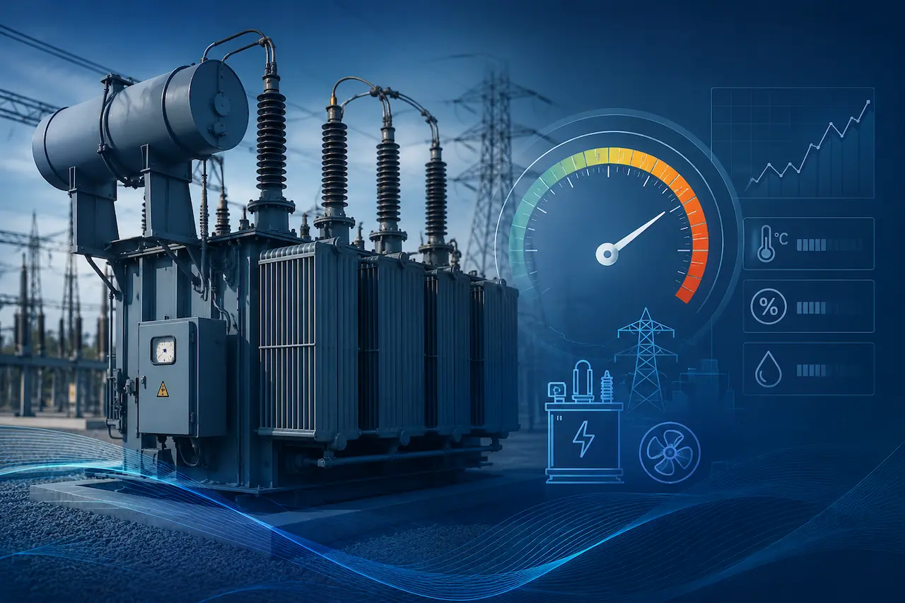
Power transformers are the most expensive and difficult-to-replace components in the bulk power system. A single large power transformer (345/138 kV, 500 MVA) can cost several million dollars, require 18-24 months lead time for replacement, and represent an irreplaceable bottleneck for power delivery if it fails. Understanding how to safely load and when necessary, safely overload power transformers using the IEEE C57.91-2011 loading guide is one of the most valuable skills in a power system engineer’s toolkit.
What Is IEEE C57.91-2011?
IEEE C57.91-2011 is the IEEE Guide for Loading Mineral-Oil-Immersed Transformers and Step-Voltage Regulators. It provides the technical methodology for calculating transformer temperatures under varying load conditions, determining maximum permissible loading for defined risk of loss of life, and planning emergency overload operations.
The fundamental insight of IEEE C57.91 is that transformer thermal aging is a function of hotspot temperature specifically, the winding hotspot temperature at the hottest point in the transformer winding. The Mont singer rule, empirically validated over decades of transformer operation, establishes that:
Transformer insulation life is halved for each approximately 6-8°C increase in hotspot temperature above the rated temperature.
This relationship means that a transformer can be overloaded significantly for short durations without meaningfully affecting its overall service life provided that the overload is carefully managed and the hotspot temperature is monitored.
Need Engineering Support for Your Power Project?
American Power Engineers delivers power system studies, substation design, renewable energy engineering, BESS projects, NERC compliance, MEP engineering, and POI interconnection services.
Explore Our Engineering ServicesThe Two-Equation Model: Top-Oil and Hotspot Temperature
IEEE C57.91 uses a two-equation thermal model to compute transformer temperatures under any load condition:
Top-Oil Temperature Rise
The top-oil temperature rise above ambient (ΔθTO) is computed as:
ΔθTO = ΔθTO,R × (K² × R + 1 / R + 1)^n
Where:
- ΔθTO,R = Rated top-oil temperature rise (from nameplate/test report)
- K = Load factor (per unit of rated current)
- R = Ratio of load losses to no-load losses at rated load
- n = Empirical constant (typically 0.8 for ONAN/ONAF, 1.0 for OFAF/ODAF cooling modes)
Winding Hotspot Temperature Rise
The hotspot temperature above top-oil (ΔθH) is computed as:
ΔθH = H × ΔθWR × K^(2m)
Planning a Solar, Wind, BESS, or Grid Interconnection Project?
Our engineering team helps project owners, developers, utilities, and facility teams move from technical planning to reliable project execution.
View Engineering ServicesWhere:
- H = Hotspot factor (typically 1.1-1.3, from transformer design data or default values)
- ΔθWR = Rated winding gradient temperature rise
- m = Empirical constant (0.8-1.0 depending on cooling mode)
The maximum hotspot temperature is then:
θH = θA + ΔθTO + ΔθH
Where θA is the ambient temperature.
Loading Limits: What IEEE C57.91 Allows
IEEE C57.91 establishes three categories of transformer loading:
Normal Life Expectancy Loading
Loading that results in a hotspot temperature not exceeding 98°C (for transformers with 65°C average winding rise design). Under these conditions, transformer insulation aging proceeds at the normal rate, and the transformer achieves its designed service life.
Planned Loading Beyond Nameplate
For planned operational scenarios where load exceeds nameplate rating for defined durations, IEEE C57.91 allows hotspot temperatures up to 110°C for durations up to several hours per day. This loading accelerates insulation aging but may be justified by operational requirements, provided the cumulative aging is tracked and factored into the asset management plan.
Emergency Loading
For genuine emergency conditions (loss of another transformer, restoration following a major outage), emergency loading to hotspot temperatures up to 130°C is permitted for limited durations. Emergency loading causes significant insulation aging and should be treated as exceptional.
Practical Application: Calculating ONAN Rating for a Specific Scenario
Consider a 345/138 kV, 200 MVA transformer with the following nameplate data:
- Top-oil temperature rise at rated load: 35°C
- Average winding rise: 50°C
- No-load losses: 200 kW
- Load losses at rated load: 800 kW
- Hotspot factor H: 1.3
For an ambient temperature of 35°C and a load factor K = 1.15 (15% overload):
R = 800/200 = 4.0 ΔθTO = 35 × ((1.15² × 4 + 1) / (4 + 1))^0.8 = 35 × (6.29)^0.8 = 35 × 4.89 = 171… [computed: ~171 × fraction]
This calculation framework is implemented in our power system studies software and can be applied to any transformer given the required design data from the manufacturer’s test report.
Application to NERC FAC-008 Facility Ratings
IEEE C57.91 is the basis for establishing NERC FAC-008 compliant transformer ratings for bulk electric system facilities. The FAC-008 standard requires that transformer ratings reflect actual capability under defined operating conditions, including:
- Normal ratings: Maximum continuous loading for defined ambient conditions
- Emergency ratings: Maximum loading for defined emergency duration (typically 4 hours) and acceptable loss of life
Our power system studies team provides FAC-008 transformer rating documentation that satisfies NERC audit requirements and ensures your facility ratings reflect actual equipment capability.
Dynamic Thermal Model for Real-Time Applications
Beyond the steady-state calculations described above, IEEE C57.91 also provides a dynamic thermal model for computing hotspot temperature as a function of time-varying load and ambient temperature. This model is implemented in:
- Advanced metering systems that provide real-time hotspot estimates from load current and ambient temperature measurements
- Energy management systems that use dynamic ratings to manage loading in real time
- Post-event analysis tools that reconstruct hotspot temperature history from SCADA data following overload events
Real-time dynamic thermal monitoring allows transmission operators to safely exploit emergency loading capability with precise knowledge of the accumulating loss of life rather than conservative static ratings that may substantially understate actual capability.
Final Thoughts
IEEE C57.91-2011 turns transformer loading from a guessing game into an engineering calculation. The core idea is simple even though the math looks dense: insulation life is governed by hotspot temperature, and that temperature can be predicted accurately enough to plan real operational decisions around it — whether that’s squeezing extra capacity out of an existing unit, setting defensible normal and emergency ratings for NERC FAC-008, or knowing exactly how far a transformer can be pushed during a genuine system emergency.
For a component this expensive and this hard to replace, that predictability matters. A transformer that’s been quietly underloaded for years because nobody ran the numbers represents capacity sitting idle. A transformer pushed past its limits without a hotspot calculation behind it represents risk nobody quantified. IEEE C57.91 closes that gap but only when it’s applied with real design data, correct ambient and cooling-mode assumptions, and disciplined tracking of cumulative aging rather than one-off calculations.
FAQs
1. Can I apply IEEE C57.91 to any oil-filled transformer, or only large power transformers?
The guide covers both power transformers and distribution transformers, but the loading margins and risk tolerance are different for each. A distribution transformer serving a residential feeder can often absorb short, repeated overloads with minimal practical consequence, since a shortened life still leaves decades of service. A 345/138 kV bulk power transformer is a different conversation entirely the replacement lead time and cost mean every degree of hotspot temperature above rated needs to be justified and tracked. Before applying the standard’s equations to a specific unit, confirm which insulation system it uses (65°C or the older 55°C average winding rise) and pull the manufacturer’s heat run test data rather than relying on default constants.
2. What happens if I don’t know the exact loss values (R) or hotspot factor (H) for my transformer?
IEEE C57.91 provides default values you can use when design-specific data isn’t available — for example, a hotspot factor of 1.1 for distribution transformers and up to 1.3 for larger power transformers. These defaults are conservative by design, so they’ll understate how much overload capability actually exists. If a transformer is a candidate for regular planned overloading (not just emergency use), it’s worth requesting the factory test report or commissioning a heat run test to get the real R, H, and gradient values — the difference between default and actual figures can be the difference between a transformer sitting idle at 90% capacity or safely carrying 115%.
3. Does ambient temperature change these calculations significantly?
Yes, and it’s one of the most common oversights. IEEE C57.91’s base assumptions are built around a moderate ambient temperature, so a transformer operating in a desert substation or a site regularly seeing 40°C+ summer days needs the ambient correction applied before any load factor is calculated — otherwise the projected hotspot temperature will be understated. For hot climates, this usually means either derating the nameplate capacity, upgrading to forced-air or forced-oil cooling (ONAF/OFAF), or both.
4. How is IEEE C57.91 different from the IEC 60076-7 loading guide?
Both standards use the same underlying physics — top-oil rise plus hotspot gradient — but they reference different hotspot temperatures and aging acceleration curves. IEEE C57.91 is generally built around a higher reference hotspot temperature than IEC 60076-7. For projects with equipment or engineering teams spanning both standards, this difference is worth flagging early, since a loading plan that looks acceptable under one standard’s assumptions can come out differently under the other, and utility audits will expect the calculation to match the standard the facility is rated under.
5. Is emergency loading at 130°C actually safe for the transformer?
It’s “safe” in the sense that IEEE C57.91 permits it for limited durations under genuine emergency conditions, but it is not free. Loading at that hotspot temperature accelerates insulation aging substantially compared to normal loading, and it should be reserved for real contingencies like the loss of a parallel transformer during restoration rather than used as a routine planning tool. Every emergency loading event should be logged and factored into the transformer’s cumulative loss-of-life tracking, since repeated emergency events can compound faster than the underlying aging curve would suggest for a single isolated event.
Transformer Loading Study Consultation | WhatsApp
Related Services:
Work With American Power Engineers
Expert engineering support for power system studies, substation design, renewable energy projects, BESS engineering, NERC compliance, MEP engineering, and POI interconnection services.
Explore All Engineering Services