
Utility-Scale Solar Farm Engineering: From Site Assessment to Commercial Operation
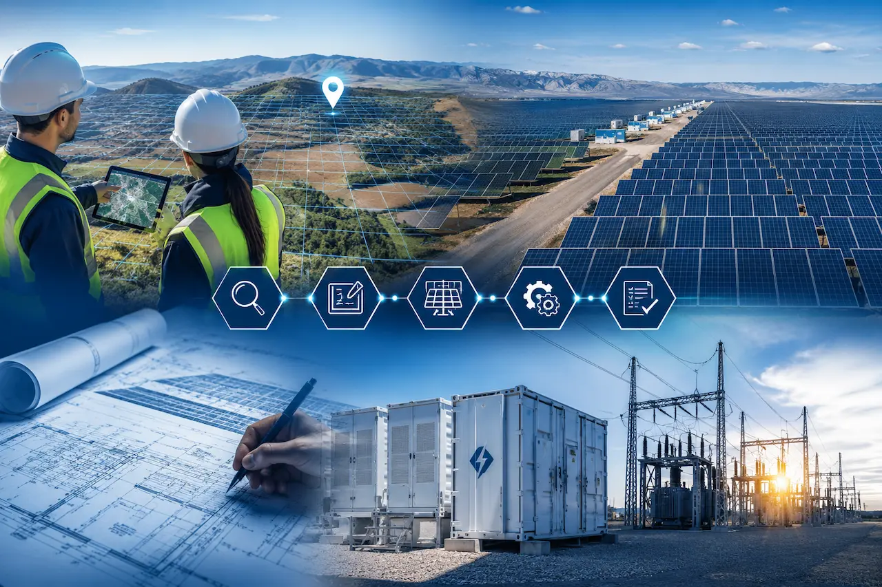
The engineering of utility-scale solar photovoltaic facilities has matured enormously over the past decade, but the complexity of bringing a 100+ MW solar project from greenfield site to commercial operation has, if anything, increased. More stringent interconnection requirements, higher transmission system IBR penetration levels, and rising lender technical due diligence standards all demand a higher level of engineering rigor than was typical even five years ago.
This guide covers the complete engineering process for utility-scale solar farms, from initial site and resource assessment through NERC compliance and operational optimization.
Site Assessment and Solar Resource Analysis
Irradiance Data Sources and Analysis
The economic viability of a solar farm depends fundamentally on the solar resource at the site. Primary irradiance data sources used in engineering-grade resource assessments include:
Satellite-Derived Data (NASA POWER, Solargis, Vaisala): Multi-year hourly time series data derived from satellite imagery. Provides broad geographic coverage with consistent methodology but requires ground-truth validation for high-accuracy applications.
Ground Measurement Stations (NOAA NSRDB, WRDC): Historical data from surface measurement stations. High accuracy where stations exist but with limited geographic density.
Need Engineering Support for Your Power Project?
American Power Engineers delivers power system studies, substation design, renewable energy engineering, BESS projects, NERC compliance, MEP engineering, and POI interconnection services.
Explore Our Engineering ServicesOn-Site Measurement Campaigns: For projects above approximately 50 MW, lender due diligence standards increasingly require at least 12 months of on-site irradiance measurement to validate satellite-derived data and characterize site-specific effects (horizon shading, albedo, soiling).
The key irradiance metrics analyzed include:
- Global Horizontal Irradiance (GHI): Total irradiance on a horizontal surface
- Direct Normal Irradiance (DNI): Irradiance from the sun’s direct beam
- Diffuse Horizontal Irradiance (DHI): Diffuse sky radiation
- Plane of Array Irradiance (POA): Irradiance on the tilted module surface (computed from GHI, DNI, DHI for a specific tilt and azimuth)
PVsyst Energy Modeling
PVsyst is the industry-standard software for utility-scale solar energy production modeling. Version 8 (PVsyst V8) introduces improved bifacial modeling capabilities, enhanced tracker modeling, and updated loss decomposition analysis.
A complete PVsyst energy model for a utility-scale project requires:
System Configuration Input:
- PV module specifications and degradation model
- Inverter efficiency curves and operating voltage/power limits
- DC cabling topology and conductor sizing
- Transformer losses (MV/HV transformation efficiency)
- AC connection losses up to the POI
Loss Decomposition Analysis: The PVsyst output includes a detailed loss tree identifying each contributor to the gap between incident irradiance and exported energy:
Planning a Solar, Wind, BESS, or Grid Interconnection Project?
Our engineering team helps project owners, developers, utilities, and facility teams move from technical planning to reliable project execution.
View Engineering Services- Irradiance losses (horizon shading, near shading from inter-row, soiling)
- PV module losses (temperature, irradiance level, module quality)
- DC system losses (mismatch, ohmic, MPP tracking)
- Inverter losses (efficiency at partial load, clipping)
- AC system losses (transformer, cable)
- Availability losses (planned maintenance, forced outage)
The Performance Ratio (PR) — the ratio of actual energy output to the theoretical maximum for a lossless system at the same irradiance — is the primary metric for comparing alternative system designs and benchmarking operational performance.
ASTM E2848 Performance Testing
ASTM E2848-13 is the standard test method for reporting photovoltaic non-concentrator system performance, used to assess whether an operating solar facility performs as contractually promised. The standard uses a Regression Testing Approach (RTA) that:
- Collects simultaneous measurements of AC power output, plane-of-array irradiance, and ambient temperature over an extended operating period
- Performs statistical regression to determine actual system performance at Standard Reporting Conditions (SRC: 1000 W/m² POA, 20°C ambient)
- Compares measured SRC performance to the Reported Test Condition (RTC) guarantee from the EPC contractor
ASTM E2848 testing is required by many PPA and financing agreements as a condition for Substantial Completion payment and performance guarantee demonstration. Our team provides independent ASTM E2848 assessment services for utility-scale solar owners and lenders.
Collector System Design for Utility-Scale Solar
The collector system the medium-voltage infrastructure that aggregates inverter output and delivers it to the collector substation is one of the most complex and cost-impactful elements of solar farm design.
Underground Cable Collector Systems
Most utility-scale solar farms use underground medium-voltage cable collectors (typically 34.5 kV) for several reasons:
- Reduced land use compared to overhead line collectors
- Lower visual impact and permitting complexity
- Protection from weather and wildlife
- Better aesthetics for neighboring communities
Cable collector design requires:
Cable Ampacity Analysis: The thermal rating of underground cables depends on soil thermal resistivity, burial depth, conductor size, insulation type, and the mutual heating from adjacent cables in the same trench. IEEE/ICEA standard ampacity calculations (or finite element thermal analysis for complex configurations) determine the maximum current each cable circuit can carry.
Voltage Drop Analysis: Solar farms with long collector circuits must verify that DC bus voltage variations and MV voltage drops do not exceed inverter and transformer operational limits.
Harmonic Analysis: The aggregate harmonic current injection from hundreds of inverters must be assessed against IEEE 519 limits at the POI and at intermediate capacitor bank installation points.
Protection Coordination: Feeder protection relays at the collector substation must coordinate with fuses or electronic fault limiters at each inverter pad-mount transformer.
IBR Interconnection Studies for Solar Projects
Connecting a utility-scale solar farm to the transmission grid requires completing a comprehensive suite of interconnection studies. Our POI interconnection engineering services cover the full study scope:
System Impact Study (SIS): Assesses the network-wide impact of the solar project on thermal limits and voltage profiles under N-1 and N-2 contingency conditions.
Short Circuit Contribution Study: Quantifies the fault current contribution of the solar farm’s IBRs during three-phase and single-phase fault conditions, for use in protection setting coordination.
Power Quality Study (Harmonic Analysis): Verifies that aggregate harmonic injection meets IEEE 519 limits at the POI.
Dynamic Stability Study: Confirms that the solar plant’s control systems do not introduce control interactions or oscillations when connected to the transmission system.
EMT Study: For projects in areas of high IBR penetration, PSCAD-based EMT studies verify ride-through performance and control system compatibility with the local grid.
NERC Compliance for Solar Farm Owners
Utility-scale solar farms connected to the BES face a comprehensive set of NERC reliability standards obligations. Key applicable standards include:
NERC PRC-029-1: IBR ride-through requirements (see our PRC-029-1 guide) NERC MOD-026-2: Generator model verification for voltage control systems IEEE 2800-2022: Performance requirements for transmission-connected IBRs (see our IEEE 2800 guide) NERC FAC-002: Transmission planning data requirements NERC CIP: Cybersecurity standards for facilities with electronic security perimeters
Our NERC compliance services provide comprehensive support for solar farm owners navigating these obligations.
Operational Performance Monitoring and Optimization
After commercial operation begins, systematic performance monitoring is essential for maximizing energy production and meeting performance guarantee obligations.
Performance Ratio Monitoring: Real-time comparison of actual PR against expected PR (from PVsyst model) identifies soiling, equipment degradation, and operational issues.
Equipment Availability Tracking: Monitoring inverter and tracker availability rates enables proactive maintenance scheduling and warranty claim support.
Degradation Analysis: Systematic comparison of year-over-year normalized production identifies accelerated module degradation and guides module replacement decisions.
Grid Curtailment Analysis: Separating curtailment-caused energy loss from equipment-caused loss is essential for accurate availability calculation and performance guarantee compliance.
Contact American Power Engineers for utility-scale solar farm engineering support, from initial feasibility through ongoing O&M support.
Services:
- Utility-Scale Solar Farm Engineering
- POI Interconnection Engineering
- Power System Studies
- Substation Design
- NERC Compliance Services
Work With American Power Engineers
Expert engineering support for power system studies, substation design, renewable energy projects, BESS engineering, NERC compliance, MEP engineering, and POI interconnection services.
Explore All Engineering Services